//ArrowChat Code
Page 12 of 38 FirstFirst ... 2 10 11 12 13 14 22 ... LastLast
Results 166 to 180 of 563

Thread: Putting things in places they ought not to be (250R Hybrid Motor build)

  1. #166
    Billy Golightly's Avatar
    Billy Golightly is offline Always finding new and exciting ways to not give a hoot in hell Catch me if you can
    Join Date
    Sep 2002
    Location
    Live Oak, FL
    --
    15,066
    Blog Entries
    14
    Okay. This thing is still driving me insane.

    Atleast when you used the pipe already rolled out round as metal and cut pieces out, you didn't have this problem as bad, all though you still did because it ovaled and changed shapes while you were trying to cut it, or you could not complete a perfectly straight edged cut like I mentioned before with the band saw blade flexing and walking side to side, it ends up more of a wave pattern in the experiences I had. Although from looking at these patterns, I'd almost be willing to go back to working directly with the steel, as the edges matched up considerably better than what I'm seeing here with the paper, but they still sucked.

    Click image for larger version. 

Name:	170081_10150090367784237_1266731_o.jpg 
Views:	404 
Size:	169.2 KB 
ID:	191059Click image for larger version. 

Name:	20140316_161130.jpg 
Views:	415 
Size:	2.03 MB 
ID:	191056Click image for larger version. 

Name:	20140316_161122.jpg 
Views:	414 
Size:	2.15 MB 
ID:	191057Click image for larger version. 

Name:	20140316_150551.jpg 
Views:	416 
Size:	2.39 MB 
ID:	191058

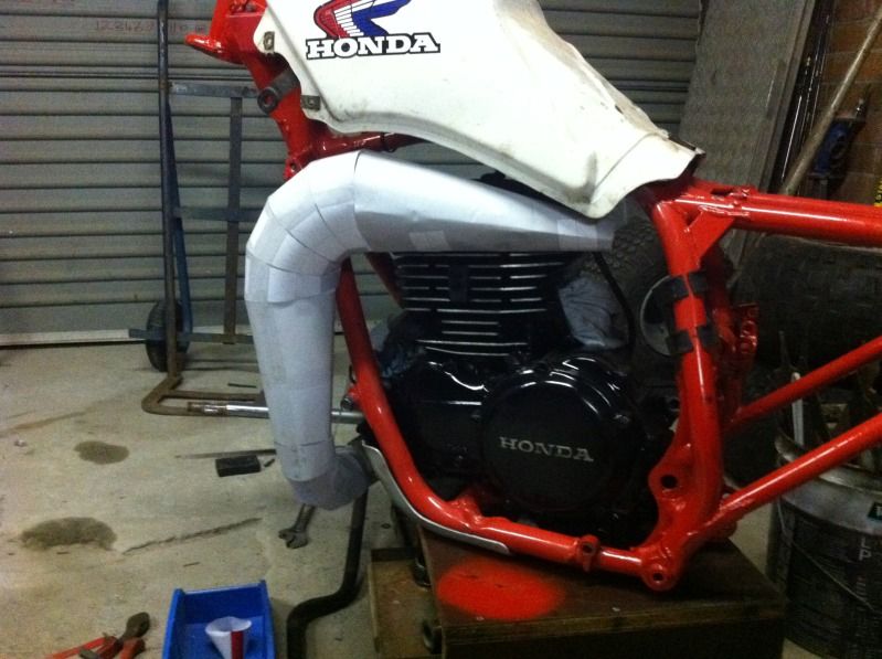
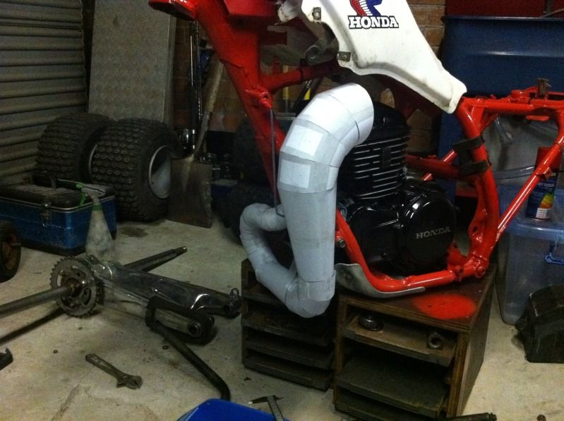
    This is with an old CR500 pipe cone I had laying around for a previous project and never used. It came to me as in the first picture, already rolled and welded down the center. I started again with this piece on the Rotax as an experiment and a trial/error type deal more than anything. I wasn't really satisfied with the results of how the joints matched up on it, because I kept running into the "ovaling" issue of the pieces, and the fact that the cut edges werent square enough to weld nicely. I could certainly cover the gaps and do it - it just wouldn't look very pretty.

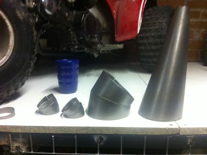
    Here is an example of what I'm fighting with trying to figure out. I understand the problem, its the fact that I'm cutting the shape on one plane, and then basically trying to use it on another, and thats why its doing what its doing. HOWEVER, I cannot figure out how to remedy that yet... How else do you cut it without it being laid flat? Initially I tried with scissors and that was even worse because then it wasn't a constantly circle around, it really waved and crooked as you worked your way around. So, I got the cutting board, that seems to have helped because atleast now its consistently wrong all the way around instead of having high and low places in it, wherever.


    Click image for larger version. 

Name:	20140412_115316.jpg 
Views:	398 
Size:	152.8 KB 
ID:	191051

    So Basically, I set my angle (Which is about 10-12-15 degrees on average I'm seeing) and I make an angled cut, where the cut edge is perfectly straight, using the paper cutter board, as you can see by the picture above.

    But what happens when you "unfold" it, and make it round, again?


    Click image for larger version. 

Name:	20140412_115305.jpg 
Views:	394 
Size:	162.2 KB 
ID:	191052

    Your what was previously nice and straight cut edge, now has an incredible bevel along the edges, that won't match up with anything. A pretty significant bevel too, as you can tell. The larger your diameter, the more pronounced it is, and it isn't just a matter of hitting that piece on a belt sander or something to even it out I don't think, the amount of material removal would be too great (so I think at the moment anyways, someone tell me something different?).

    Click image for larger version. 

Name:	20140412_115331.jpg 
Views:	397 
Size:	195.2 KB 
ID:	191054

    Another example, of a sectioned off piece of the card board template, perfectly straight cut edge.

    Click image for larger version. 

Name:	20140412_115233.jpg 
Views:	393 
Size:	162.9 KB 
ID:	191055Click image for larger version. 

Name:	20140412_115129.jpg 
Views:	395 
Size:	144.9 KB 
ID:	191053

    Now, rolled back out into a circular shape - this is what I get.


    I understand this is a by-product of cutting it on one plane and axis like I mentioned above, and then changing it, but how in the hell do you cut it on the round plane to begin with?! The paper has to be flat to cut it., and if you use scissors, your even more cattywompass from what I'm seeing. I really thought that this method would allow me to then trace out the metal pieces and make it all be nice and perfect...no such luck Where I seem to be at, at the moment, is able to resolve one issue or another. I can fix the ovaling, or I can fix the mating edges, but I can't seem to get both fixed together. I half way wonder if on the steel pipe, it wouldn't be prudent to cut each one of those sections apart, and then re-roll them by hand, and then re-weld them


    What in the hell do I do here? I'm sure the answer is simple but it sure is doing a good job of hiding from me.

  2. #167
    Join Date
    Oct 2002
    Location
    Northeast
    --
    17,438

    Cool

    Whats being tricky for Billy, some may not understand; I can explain it like this.

    Chop off a piece on the bottom of a coffee can, both the top and bottom may measure 4"s OD. Now cut or sand 1/4" off ONE SIDE to a taper to the original height on it's opposing side, NOT opposing end. Now this opening may measure 4.250 because it is now a greater distance due to the angled cut.

    Hence the difficult welding work trying to keep gaps tight. Not easy to do......

    At least that's my thought....

    Looking good Billie!
    All our government does is distract us while they steal from us, misspend our tax $ and ruin our country

  3. #168
    mart is offline *CERTIFIED* Mad Scientist Arm chair racerAt the back of the pack
    Join Date
    Apr 2003
    Location
    newcastle australia
    --
    271
    A layout will not be a straight cut like that for a cone billy.
    The best bit of advice I can give you is honestly download that little program I mentioned (cone layout)
    Punch in length of cone front angle rear angle front diameter rear diameter an it prints it out for you. One one is printed I guarantee you'll understand how the layout is ment to be an it'll all come together.
    Here's a few of a pipe I did for my aircooled (never got it finished though lol )


    Little vice mount slip rolls are all you need


    You'll work it out I bet as soon as you print one you'll be like I'm a bloody idiot I knew that's what I had to do lol good luck my friend.
    MARTS 84 300R 86 250R 700r raptor & suspended 250r in 70 frame

  4. #169
    Billy Golightly's Avatar
    Billy Golightly is offline Always finding new and exciting ways to not give a hoot in hell Catch me if you can
    Join Date
    Sep 2002
    Location
    Live Oak, FL
    --
    15,066
    Blog Entries
    14
    Hey Mart,

    I've got the program - but I was really only able to use it to develop the templates for the full length of each section. I know you can change angles with it and stuff, but how do you make it divide up the total length, and keep the same degree of taper? Like in my screenshot here, The cone modeled is the "A2" section, on the dimensional chart on the left in the screen shot. And in the picture below of the cardboard template I made, its the second piece from the right. But how do you make the program divide the length of that down into multiple parts? I know this has to be silly simple but I just can't seem to get my head wrapped around it...

    Click image for larger version. 

Name:	Screenshot.jpg 
Views:	394 
Size:	455.7 KB 
ID:	191061


    Click image for larger version. 

Name:	PaperTemplate.jpg 
Views:	385 
Size:	104.6 KB 
ID:	191060

  5. #170
    Join Date
    Oct 2002
    Location
    Northeast
    --
    17,438
    Billy, I think that paper exhaust may get a bit hot!!

    Hope that program helps you out, I wanna see this beast!

    DC
    All our government does is distract us while they steal from us, misspend our tax $ and ruin our country

  6. #171
    Billy Golightly's Avatar
    Billy Golightly is offline Always finding new and exciting ways to not give a hoot in hell Catch me if you can
    Join Date
    Sep 2002
    Location
    Live Oak, FL
    --
    15,066
    Blog Entries
    14
    Okay, after having slept on this (with a migraine, but I digress) I've made a little bit of progress mentally. I *think* where I'm short here is a mathematical formula that Mart probably has or figured out, in order to DIVIDE my cones into sections.

    Lets say for example the first major tapered section of my pipe are the following dimensions;

    47mm Entry Diameter,
    530mm in Length
    90mm Exit Diameter

    So lets say I want to make this tapered cone of the pipe into 20 equal sections. I can divide 530mm by 20, and I end up with each sectioned piece being 26.5mm in length.

    However, my current stumbling block is figuring out and calculating the entry, and exit diameters for each one of these 20 sections.

    If I figure that out, I can then plug the dimensions into ConeLayout, with my desired angles, and I can print each individual section on a template like Mart did. Or, like I seen Arlan from LED Performance do on his Facebook https://www.facebook.com/pages/LED-P...569?fref=photo (FYI, if you look really close in this picture from him, you can see the same little template indicator that Mart has in his pictures from Cone Layout) So I'm just missing this one very piece of crucial math..

    Click image for larger version. 

Name:	LEDBansheePipe.jpg 
Views:	360 
Size:	99.1 KB 
ID:	191134


    If there are any math gurus that want to explain this to me, or all of us, please, feel free

  7. #172
    Join Date
    Oct 2007
    Location
    Minneapolis mn
    --
    4,067
    I don't understand the math, but love the direction you are going... Hang in there Billy, you have almost got it licked!
    No trikes. Too old, too crippled. Unless I find one I can't live without!
    "You cant fix stupid" ~ Ron White
    My feeback link: http://www.3wheelerworld.com/showthr...ack-for-Thorpe

  8. #173
    Billy Golightly's Avatar
    Billy Golightly is offline Always finding new and exciting ways to not give a hoot in hell Catch me if you can
    Join Date
    Sep 2002
    Location
    Live Oak, FL
    --
    15,066
    Blog Entries
    14
    I've been quizzing a few people about the math on this, Its definitely above my pay grade also, but the best response I have thats sort of leading me in the right direction so far is something that amounts to calculating the volume of the cone (Which is actually I learned technically called a "Frustum" since it doesn't come to an exact point. There are conical frustums and pyramid frustums.) and then using what I guess is come calculus (way, way above my pay grade) to graph it using an integral and then using degree of angle the side taper is to calculate each piece individually based on the heights, starting at the bottom and working your way up. Which is pretty much exactly what I'm needing to do I think, but even though this person explained it to me in laymans terms, I still have no idea how to do it...

    This page helps me understand a little bit, but still doesn't answer my question really, per say...http://www.calculatorsoup.com/calcul...calfrustum.php


    I also posted this question in the math section on Yahoo Answers out of shear desperation.

  9. #174
    Join Date
    Mar 2013
    Location
    Baldwin, Wi
    --
    603
    Billy,

    Not that you are looking for this technique at all but with all your knowledge on metal fab something like this might interest you. I just stumbled across youtube surfing.

    https://www.youtube.com/watch?v=ppXRMTeR2NQ
    85 Tri-z Power valve on Inverts
    85 Tri-z Basket Case
    01 gsxr750 engine/Tri-z frame (long long way from complete)

  10. #175
    Billy Golightly's Avatar
    Billy Golightly is offline Always finding new and exciting ways to not give a hoot in hell Catch me if you can
    Join Date
    Sep 2002
    Location
    Live Oak, FL
    --
    15,066
    Blog Entries
    14
    I think I might have this one cracked. It works on paper, but I am going to be printing some templates across the next few days to verify and know for sure.

  11. #176
    C.J is offline Just Too Addicted Arm chair racerJust too addicted
    Join Date
    Apr 2011
    Location
    Central, Louisiana
    --
    639
    Quote Originally Posted by Billy Golightly View Post
    I think I might have this one cracked. It works on paper, but I am going to be printing some templates across the next few days to verify and know for sure.
    Ok Billy,, this thread was on the bottom of the second page that's no bueno!!!! Lol


    Any progress on your crack pi-I mean pipe building theory yet? DID IT WORK OR DID YA HAVE TO GET A BIGGER HAMER?!
    too many bikes to count. too little time on hand.

  12. #177
    Join Date
    Sep 2010
    Location
    NEPA
    --
    7,048
    Whew. I hadn't seen the pipe updates till now..Makes a $900 custom 500R pipe look cheap! If I was you Billy, I wouldn't be able to quit till I saw this through also.. But wow. What a learning curve. That paper pipe is a thing of beauty. I can't wait to see the real deal!
    Please help those who cannot help themselves.

    ALWAYS buying Museum quality machines,3 and 4 wheels. And any and ALL ,NOS parts,EVERY brand.

    I am turning my PM's Off,my Email is billsracing@hotmail.com,put 3WW in the subject. Thanx!

    Gun laws do not stop criminals. BULLETS do.

  13. #178
    Billy Golightly's Avatar
    Billy Golightly is offline Always finding new and exciting ways to not give a hoot in hell Catch me if you can
    Join Date
    Sep 2002
    Location
    Live Oak, FL
    --
    15,066
    Blog Entries
    14
    Everytime I think I have it licked, I find a new and exciting way to further complicate it

    Really though, I just need a good solid day or two to screw with it. I have not really had the time to unfortunately. Good news is, I did get my printer at home working again, so I can do templates on the fly (vs having to model up at home, pdf, and print them at work like I was before). Instead of printing paper and tracing over to construction paper board and cut templates out with scissors, I'm going to get some 8.5x11 sheet of that construction paper and print directly on it. It'll save me a step in trying to trace and cut things out basically twice in a row.

    Dividing up into sections I've figured out. What I need now is to use the paper templates in a real world application and decide whether I need to divide say a 350mm long section into 20 pieces the entire length of the 350mm, or make it be 15 pieces until the last 6 inches, or the middle 6 inches, or wherever. Basically I have to determine where I *dont* need to section and can use just a straight section. Which, on this pipe, isn't going to be very much.

    My methodology for doing that at this point is to divide up the entire length of each taper into equal parts, print templates, and then as I'm building it on the bike, just count to whatever section # I'm at that can be straight afterwards (for whatever length), then go back into the template program, and basically say "Okay, instead of having the next 6 sections be 22mm in length, with a 15 degree slice on each end, I can have one piece, 132mm long with a 0 degree slice on one end, and then a 15 on the other". That'll eliminate a lot of unnecessary parts (to just go straight), and welding for me. Because right now as I have it calculated out, I'm at 54 sections without the stinger tube, or the exhaust port flange sleeve. So, if i can knock that down any, by all means, I want to do it.

    Something else I ran into, is that early on I figured I'd find a nice width for a section (I settled on about 22mm) that would give me enough width to get 15 degree slices on each end of the each section without the narrow side being impossible to weld, basically. So I'd calculate out the entire length of a taper into 22mm sections. Well, what would then happen when I got into my template program, I found as the pipe got larger, the slices at that same consistent 15 degrees made the thinner side thinner and thinner, until it wasn't possible because each 15 degree side would overlap ( Like this /\ basically). So, I had to increase my width of my sections as the pipe got larger in diameter.

    Speaking of that, since i don't particularly believe in trade secrets, I'll explain how to section the pipe up equally. This might be a little bit difficult without a drawing, but you can probably follow it as the math is really very elementary, and like normal, I was over-complicating things by a significant degree. I have to thank a guy at my office, Irvin Dees, for basically taking this home and figuring it out for me in one night because I for the life of me couldn't get it...

    So lets use the first main taper section of my real world exhaust I'm doing to be building, the specs are;

    530mm long. 47mm Entry, 90mm Exit.

    First, decide how many sections you want. Lets say you want each section to be about the same 22mm in length I'm using. So you'd divide 530(The length of the original full tapered section) by 22mm. That gives us on the calculator, 24.090 pieces. Obviously, I can't make .09 of a section, I need a round number. But 24 pieces is darn close - so you take 530/24=22.08mm. In a real world application, 1mm is about .043. .08 of 1mm is not even a gnats ass, but for calculating purposes, I suggest keeping the two decimal points or you can get lost pretty easily.


    Next, You take the exit diameter, and subtract the entry diameter from it. 90-47=43. This is the difference between your entry and exit diameters.

    Then, you take that 43mm, and divide it by your amount of sections you want. So it'd be 43/24=1.79

    This 1.79mm, is the ADDITIONAL INCREASE in each section, from the previous diameter, as long as you keep each section exactly 24mm in length, since the taper is at the same constant angle from start to finish. If you change the length of any of the sections, you have to re-calculate.

    So, the very first piece of this pipe coming off the exhaust flange I now know will be;

    #1: 47mm entry, 24mm in length, 48.79mm exit diamter
    #2: 48.79mm Entry, 24mm in length, 50.58mm exit diameter
    3 50.85mm Entry, 24mm in length, 52.37mm exit diameter.
    4
    5
    6
    etc...

    I can then take those dimensions, and plug into cone lay out, the angle of the slice I want on each end, and it spits out a nice flat pattern template like Mart, and LED have that I posted above. This is the key to making a template for each individual section I was missing. However, Keeping mindful of the issue I mentioned above, that as the diameter increases to a certain point, the length of each section as to increase to accommodate the angle of the slice from each end, so you don't run out of material. What I do is watch the templates its generating, and I scale to 100% and actually measure the narrowest portion on my monitor with a pair of calipers. If it gets below 10mm in width, I either increase the length of the piece (and re-calculate) or I lessen the angle from something like 15 degrees on each end, to something like 10 on each end.

    If I need to change the length, I just calculate the remaining length, and starting diameter from wherever I left off at. Say I'm at section #10 (So It'd be 220mm shorter from my original starting length of 530mm, leaving 310mm length). I'd know my last diameter at piece #10 was 64.90mm, so i would treat that as the start, and run through the same process I outlined above of determining how many pieces total I'd need after setting a new width, and how much to increase the diameter each time.

    There is really no way to specifically figure out this exactly without some trial and error where to put the straight sections. The first 8-10 inches or so will of course have the most sections as you do the 180 degree turn to go back under the front heading towards the right side of the bike.

    So I do not have all my sections exactly figured out until I do that, but I'm darn close. I could do all 54 pieces right now and just do the entire thing in sections, but I want to refine and get in as many straights as I can for simplicity and also aesthetics. Having a straight place made up of nothing but sectionals just counter stacked from one another would look a bit odd I think.

    Clear as mud?

    Not out of the woods yet but I definitetly have a handle on it I think. The next question becomes, once I have all these templates figured out, do I cut these things myself, or do I take the easy route and just send some water jet people my flat pattern dxf (autocad) files and say "make these for me" where all I have to do is roll and weld...
    Last edited by Billy Golightly; 04-21-2014 at 10:16 AM.

  14. #179
    Dave8338's Avatar
    Dave8338 is offline At The Back Of The Pack Arm chair racerAt the back of the pack
    Join Date
    Jan 2013
    Location
    Central MN
    --
    378
    I think you choice of having them water jetted, is the best call. Sure, you can spend the time but, do you really want to? Also, the welding will go much smoother if all the edges are perfect and uniform. Less likely to burn through and have to fill a pin hole (or worse)...

    FANTASTIC work you have going ! ! !
    The Goal... All I Need Is The Time...

  15. #180
    C.J is offline Just Too Addicted Arm chair racerJust too addicted
    Join Date
    Apr 2011
    Location
    Central, Louisiana
    --
    639
    I say experiment with your theory. At least on a couple pieces. If it works THEN spend the money to have everything cut for you. It would SUCK to spend the money and then find out it didn't work out right ya know?
    too many bikes to count. too little time on hand.

//ArrowChat Integreation Code //