
Thank you very much, how did you calculate the cones? Did you draw them with cone layout?Originally Posted by Billy Golightly


 First Time Rider
Arm chair racerNew to the board
First Time Rider
Arm chair racerNew to the board
Thank you very much, how did you calculate the cones? Did you draw them with cone layout?
First Time Rider
Arm chair racerNew to the board
Some axles after chemical nickel coating,
The Chainwheel was painted red like every detail on the trike:

First Time Rider
Arm chair racerNew to the board
A small walkaround the trike with mounted axle and wheels:

Always finding new and exciting ways to not give a hoot in hell
Catch me if you can
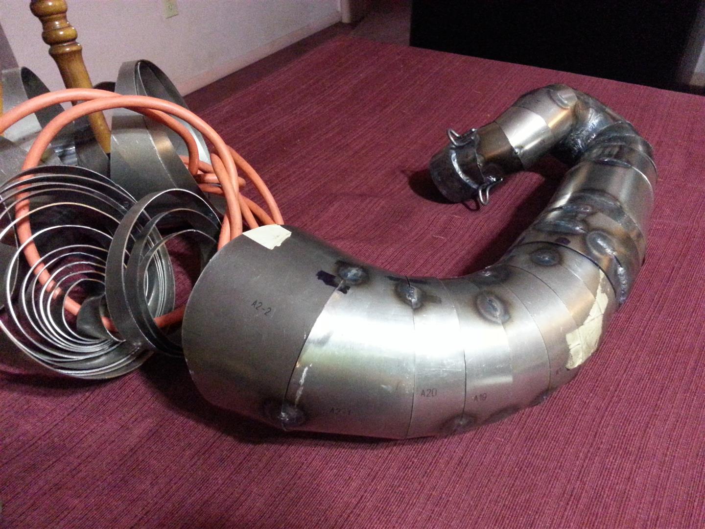
Yes. I used the 2 Stroke Pipe Wizard program (About $25 dollars) and cone layout. What took me FOREVER to understand was how to create each individual section in cone layout. Essentially, all it is, is figuring out the width (or length, as traveling down the pipe) of the section you want on average, and then dividing that into the length of the specific coned area you are dividing. Then you increase the inlet and outlet diameters of each one of those sections, that much. Its VERY easy once you understand the process, but I banged my head against the wall for weeks trying to speak to mathematicians and all sorts of people to figure out how to equally divide the cone chapes, and what the inlet and outlet diameters for each one of those sections would wind up being so I could plug the parameters into cone layout.
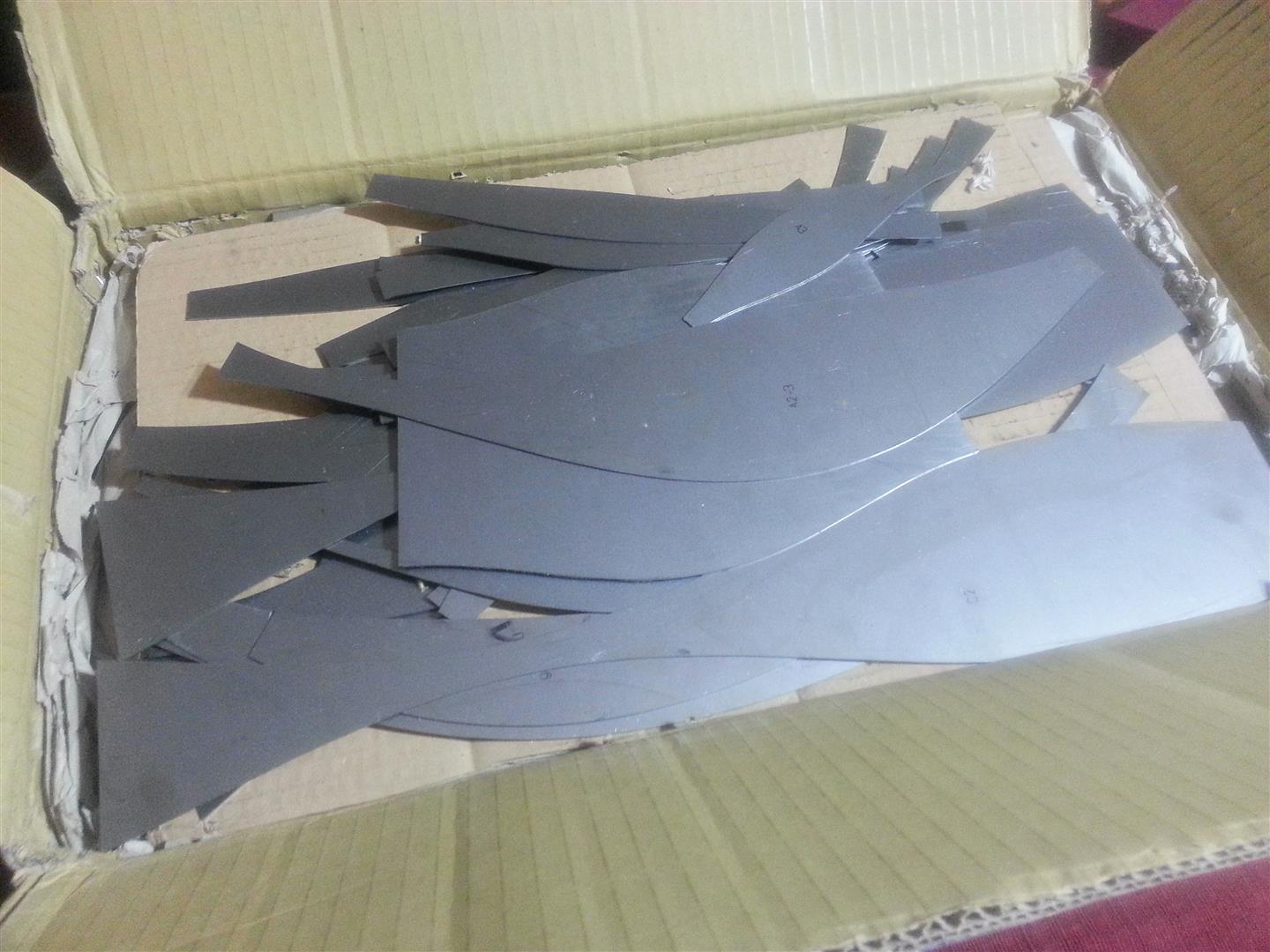
When I did mine, I actually created templates for each individual section of the pipe, versus making the entire thing straight and then band sawing pie cuts out of it which seems to be the more popular methodology. I had 54 pieces laser cut for me by German buddy Hagen, and then I hand rolled and tig welded everything together, each bend and section individually.
First Time Rider
Arm chair racerNew to the board
Thanks for sharing. You used a lot more sections then me. For my next pipe i will also built at least 40 sections. I think i used a complete new method by designing that thing in CAD. It is basicaly the "saw a straight pipe" method but it was entirely done on the pc. It was also quite puzzeling till i found a solution to devide the angles between every segment. Now this is done within an houre when the "3D scan" of the route through the trike is finished.
Did you polish the welded lines on the insied? On the pic it looks like you just welded it together. When i did that i had a lot of weld spatters on the inside...
Always finding new and exciting ways to not give a hoot in hell
Catch me if you can
Mine were all fairly clean on the inside. I did have a few a little rough but overall I was happy with it. As you mentioned, for me also, the challenge was dividing the angles for each section and knowing with exactness what their dimensions were. On the smaller diameter areas I didn't do more than a 5 degree angle on each end. On the larger pieces I went up to 15 I think, in the middle.
I really like your cad method - it is a little beyond my realm of expertise but I can definitely appreciate the modeling process and work it took to put that together in that way. Here is one more picture of mine finished as well as a link to my build thread and then you can have your thread back from me
http://www.3wheelerworld.com/showthr...ighlight=rotax
Sent from my SM-N910V using Tapatalk
Last edited by Billy Golightly; 09-08-2015 at 11:06 PM.
First Time Rider
Arm chair racerNew to the board
Great built from you, that trike looks awesome.
Dont worry about the threat, i realy like to corespond with someone who is gone that way too...
What steel and plate thicknes did you use?
Always finding new and exciting ways to not give a hoot in hell
Catch me if you can
I had two sets of everything made. One in mild steel, 1mm thick that I built this pipe out of. And then another set out of stainless steel that had been annealed for easier forming/shaping.
I have not done anything with the stainless sets yet.
New to the board
Arm chair racerNew to the board
That's some patience you have there.
First Time Rider
Arm chair racerNew to the board
Sorry for the delay of my upgrades... I am quit buisy with the building of my flat at the moment...
A pic from the zinc plated steel parts:
(They are not only for my trike)

First Time Rider
Arm chair racerNew to the board
The Carb and cooling hose was mounted:

First Time Rider
Arm chair racerNew to the board
The guards (I dont know how you guys call them!?) for my radiators were built from anodized aluminum sheets and aluminum pipes.
They hold the shrouds an protect the radiator from dirt:
after welding and cleaning:
finished:

First Time Rider
Arm chair racerNew to the board
Yes the whole built used to take about one year and three months...
First Time Rider
Arm chair racerNew to the board
Sorry for letting you wait, i had to built an stainless exhaust for my 200es, attached is a pic as excuse
A steel kickstarter was milled for the trike but then i found out that it will not clean my pipe and i had to think about a better concept for the kicker...
(thats the part of the tricke that i am not realy proud of...)
Here is my solution, it is a bent steelrod wich was welded to the cut lower pice of the milled kicker...

First Time Rider
Arm chair racerNew to the board
First test of the engine...
https://goo.gl/photos/mYbbLjio5VQbDfJv7
And the first test ride...
https://goo.gl/photos/Ri1hUd2oikothCiv6
And here you can se a beautiful pic of my technical drawing skills:


 Reply With Quote